IE030103A
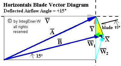
Airflow Deflection Theory Briefly
Page 2
Blade Efficiency - Not The Same As The Betz Efficiency
Now for the interesting part. The ease with which forces on the blade (both the driving force and the bendback force) and energy distributions along the blade lengths from root to tip can be calculated are powerful reasons why these analyses need to be made more well known. All of these were derived from the basic F = m dot delta V formula for the force. Our formulas give us two ways of
determining the amount of energy that is being transferred to each location
along the blade length and, thus, the resulting blade efficiency there. The
first is to look at what energy is being removed from the kinetic energy in the
wind at each blade location. The second is to look at what energy is being added to
the blade there. These two energies can then be compared. It would be well that
they turn out to be the same under all conditions. And they do. The reduction of
the kinetic energy of the wind turns out to be the same as the energy added to
the blade at every location along the blade length.
Here are the
derivations of the two energy formulas, along with the resulting formula for the blade energy efficiency, %E. Note that the variable R is defined therein as V/W1, which is otherwise known as the tangential speed ratio or TSR:
Here is the graph for the blade energy efficiency, %E, obtained from this formula that makes use of the tangential speed ratios (TSRs), identified as the variable R, and pitch angles, including 0 degrees. It is important to note that this graph may be interpreted in two ways. One is looking at the blade from the root (TSR = 0) to the tip (TSR = max). The other is looking at any one location along the blade while the rotor rotation rate changes from zero (TSR = 0) to a high rotation rate (TSR = max). This also applies to the additional graphs presented below, all of which make use of R as the graph abscissa:
Notice that at high blade speeds in relation to the wind (R
values) the blade efficiency drops off for pitch angles other than zero. For the
pitch angle of zero degrees it remains at nearly 100% up to an R value of 10 and
beyond. This has been amply verified in practice. Some still find this to be counterintuitive.
Notice also that the efficiency becomes sensitive to even very
small pitch angle changes at these high R values. It also demonstrates why a pitch
angle of zero degrees, despite the ordinary intuitive difficulty in
understanding it, can be so beneficial. Given the absence of flow separation, the blade is simply more efficient at
all R values.
"In relation to the wind" means what it says. Wind turbines
are often compared for their ability to generate energy in low wind conditions
and low wind conditions mean high R values, the same R values that pertain to
fast moving blades in better wind conditions.
This, again, is a somewhat
elementary view that does not take into account the airflow deflection at more
remote distances from the blade surfaces. If such additional air mass deflection is included in these calculations, the possibility of going to negative pitch angles (!) adds to rather than subtracts from the blade efficiencies up
to a point. But the same conclusions, in general, can be reached for this more
general case, that is, that the efficiency at high R values is sensitive to
small pitch angle differences and that a zero degree pitch angle tends to
maintain the efficiencies at a high value rather than allowing them to decrease.
These are important conclusions.
Note also that the blade efficiency is low at the blade roots, hardly worth anything at all, despite the often large blade chord widths found there. The wind may be deflected there but does not give up much energy.
The above graph can be presented again,
for only a pitch angle of zero degrees and up to a maximum value for R of 5
rather than for a higher value.
Here is what the graph looks like:
As the wind passes over the blade and is deflected it gives up its
energy and this graph shows, as a maximum, just how much. Notice that, as a rule
of thumb, the energy conversion can be seen to be quite good at an R value of 2
- about 95%. It is not bad at an R value of 1 either - about 83% - but it drops
off very quickly at a value of .5 - about 60% - and below. If good energy
conversion is required, then, it is best if all locations along the blade
lengths and during as much of the rotational cycle as possible, have velocities
equal to that of the wind crossing them or greater, preferably twice as
great.
As mentioned earlier, this is not the same as the Betz or the
overall rotor efficiency. Here we can obtain efficiencies of 100%. If these
blade efficiencies average out to low values, then they risk affecting the
overall rotor efficiency of the machine, lowering it below the Betz efficiency
despite other measures taken to keep it high.
Important Formulas Based On The R Value
Now that the parameter R has been defined (= TSR) and its importance in
relation to the efficiency of the blade in producing energy at each increment
along its length has been determined, a few more formulas can be presented that
are based on these blade increment R values as well. Accordingly, discussed
below are formulas for the blade increment driving force, the blade increment
axial or "blade bendback" force, termed the "lateral force" here, and the blade increment energy creation, this last being obtained
from multiplying the blade driving force by the blade velocity.
Once it
is clear what is happening with each blade increment along the blade lengths,
then all these increments together can be viewed as "building blocks" in being
assembled together in determining the total forces acting on the blades and the
total energy created by them. A characteristic of most of this analysis is that
it assumes no flow separation is taking place and no parasitic drag is present.
These assumptions are normally not valid in practice. At low R values
approaching zero, there normally is flow separation present unless the blade
leading edge is made to have some camber or be round and bulbous rather than
"pointy". At high R values, parasitic drag becomes noticeable, netting out some
of the driving force and thus reducing the energy delivery unless, on the other
hand, the blade leading edge is straight with no camber or is sharp and
"pointy". Clearly, it becomes difficult to satisfy both of these conditions at
the same time at the same blade location.
It also is assumed that the blade
increment pitch angle is zero. As we have seen in the above paragraphs, nonzero
pitch angles, both positive and negative, alter the forces and energy creation
in a way that is highly dependent on the value of R at its upper range of
values. For the time being we want to look at the effect of R on the blade
increment without the complication of pitch angle differences and using a pitch
angle of a nominal value of zero does this adequately enough. The effect of
pitch angle variations may be looked at separately elsewhere.
The first
formula, then, is for the blade increment driving force as is shown in the below
graph:
The formula was derived from the force formula presented on Page 1 for a pitch angle of zero. First, it is to be noticed that, for all values of R,
the driving force is generally proportional to the wind velocity squared. This
is always the wind velocity the blade sees immediately and locally at right
angles to the blade forward motion.
Once the
variation with wind velocity is is taken into account, then, the rest is easy.
When the blade is stopped or moving very slowly (low R), the value of the
multiplier factor as shown in the graph is about one. As the blade increases in
speed, the multiplier factor drops to about one half and stays there no matter
the blade velocity from then on (high R). It is characteristic of wind generator
blades, therefore, at zero degree pitch angles that they produce about twice as
much driving force or torque when they are moving slowly as when they are moving
fast.
This also applies to horizontals blade driving forces along their
lengths from root to tip (low R to high R). The driving force drops somewhat but
remains quite high at a constant value all the way out to the tip and this, of
course, encourages the lengthening of the blades in the by now classic
horizontals wind generator upgrade design process. The point of diminishing
returns occurs when the parasitic drag effects at high R values become
significant. The blade axial bendback or "lateral" forces on the blade, described next, also play a role
in limiting blade lengths. But until then little stands in the way of rotors of
larger and larger diameters that profit from this additional blade
length.
The second formula is for the blade increment "bendback" or lateral force as
shown in the below graph:
This formula was derived from the force formula presented on Page 1 for a pitch angle of zero. Again, it is to be noticed that, for all
values of R, the "bendback" (lateral) force is generally proportional to the wind velocity
squared. It is important to minimize the "bendback" (lateral) force and help is available in
either designing the blade for stall regulation or in depitching it (increasing
the pitch angle in a positive sense) to avoid excessive forces when
necessary. When the blade is stopped or moving very slowly (low R), the value of
the multiplier factor as shown in the graph is about one. As the blade increases
in speed, the multiplier factor increases and thereafter assumes a somewhat
linear increase with blade velocity (high R). This, of course, is despite the
pitch angle being zero. Again, it must be emphasized that, for a fixed wind
speed, the blade "bend-back" (lateral) force increases profoundly with blade rotational velocity, something sometimes not realized.
While the driving forces remain level out to the blade tips, as noted above, the
bendback forces, which are typically greater to begin with, go on to increase in
a linear fashion and so can reach values that are much greater by large factors.
These forces must be absorbed and accommodated since, after all, this is how
wind generator blades do their work in stopping or slowing the wind.
The third formula is for the blade increment energy creation as shown in the below
graph:
This formula was derived from the force formula presented on Page 1 for a pitch angle of zero. It is seen, of course, to be equal to the
formula for the driving force provided earlier multiplied by the blade forward
velocity. It is to be noticed that, for all values of R, the energy creation is
generally proportional to the wind velocity cubed. When the blade is stopped or
moving very slowly (low R), the value of the multiplier factor as shown in the
graph is zero or close to zero. This is also the place where the driving force
is at its maximum as discussed earlier. It is one of those odd things about wind
generator blades that those times when the blade torque is at its highest are
also the times when the energy delivery is at its lowest. This should help in
facilitating startups when necessary if measures are also taken to eliminate
flow separation.
The energy delivery by the blade increases, then, as
seen above, in a linear fashion with increasing R (high R). This same effect is
observed by sailboats when sailing close hauled in that their sails see greater
apparent winds with greater forward speeds and so, in succinct terms and to a
certain extent, the faster they go the faster they go.
Finally
Deflection Theory provides these and many other answers to wind turbine questions when approached in detail.