IE130222A
Tony Chessick
Feb 26, 2013
as
updated
May 20, 2014
Airflow Deflection Theory Briefly
Page 1
Streampaths Are Hereby Defined
Use Is Conveniently Made of
Stream Functions for this Purpose
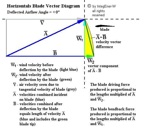
In the separate file within the same directory, a derivation for
the "Basic Streampath Force Equation" or what can be termed the "Newton's Law
For Fluid Flow":
is
provided (click here).
What it can be said to represent is a streamtube of flow with a beginning flow
velocity vector, a selected distance traveled by the flow along a streamline,
and an ending flow velocity vector. In two dimensions, this would be termed a
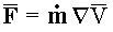
"streampath". The formula states that the force vector that this streampath, as
a whole, exerts on the surrounding flow and any flow boundaries present is equal
to the rate of mass flow within this streampath (represented as "m dot" in the
above formula) times the vector difference of the velocity vectors at the
entrance and exit (represented as "ÑV" in the above
formula). A drawing showing three important cases of "ÑV" and how to calculate it for each case is presented
below:
In
the first case, the force, F, despite the bend in the flow path, is zero. In the
second case, the force, F, is directed upwards. In the third case, the force, F,
is directed to the left. Note that forces resulting from pressure differences
from one end to the other are not accounted for. This would particularly impact
the third case above. Viscosities and friction effects, if significant, would
also have some impact.
Wind energy makes use of the second case
primarily, that is, the "flow deflection" case. The blade deflects the flow and
sees a lift force from the deflection. Note the important fact that in the blade
frame of reference, as here, the flow changes direction but not velocity.
It is, in fact, the use of vectors and vector algebra that characterizes
such an appoach to fluid flow analysis. This was not seen in earlier aviation
aerodynamics, where the lift force was always taken as vertical in graphs, any
other directions never considered. What may be borrowed here from earlier work,
though, is the stream function. If a streampath is being taken, then it must be
true that its location can be found by means of a stream function. Just take two
slightly different values of the stream function, representing two different
streamlines near each other, and find all their locations in flow space. Since
the path has some width thereby in accommodating a certain amount of massflow,
then a "delta stream function" can be readily defined, the difference between
these two stream functions near each other, i.e. Ñy(x, y) = Constant. This, then, can be introduced into
the above formula.
In this way, a different approach can be taken in
finding aerodynamic forces. Traditionally, earlier work using the kinematic
approach (that is, without considering the mass density) involving stream
functions first determined the flow velocities adjacent to a flow boundary such
as an airfoil. Then the Bernoulli Equation was used to find the pressure
distribution at the flow boundary all along its length. Then an integration was
done over the pressure distribution to find the resultant single force
acting.
Using the above "Newton's Law" formula, instead, the force can be
found directly, without determining the pressure distribution, a simpler
approach. However, it can only be used for one streampath at a time. This
assumes either that a wide streampath is taken, the flow within found as an
average, or many adjacent streampaths taken, the forces then added as vectors.
We see here that, accordingly, making use of the stream function can provide
help in using the streampath approach to find forces as well.
This new
approach lends itself to looking at the lift force in an entirely different way.
What happens is that, due to the viscosity of air, not all of the air deflected
downward at the trailing edge recycles back to the leading edge as the "gamma
circulation" in traditional theory. In fact, most of the deflected air simply
continues downward and then scatters backward instead. This, of course, carries
away with it some energy and creates some drag. It has been aptly named "induced
drag" or the "drag penalty of lift".
The Case of Wind Energy
With the above in mind, wind
turbine aerodynamics can be considered. Wind energy is somewhat different from
aviation. The parallel would be the case of the aircraft descending while flying
on its course. Then an airflow occurs upward from beneath the wings in a similar
manner as the wind approaches the blades of the turbine from the front of the
rotor. The wings then aid the engines in propelling the aircraft forward just
like the wind turbine blades turning the rotor. It should be made clear that
energy is produced that is extracted from the upward flow of air past the wings.
This is where the similarity with wind energy lies.
The circulation mode
of creation of forces, that is, the "F = rVG", is inefficient in
producing energy. I have always held some skepticism about the concept of what
is essentially just a vortex under and around the aircraft wings being able to
work such wonders. As now mentioned in recent articles on the home page of this
website, a more thorough analysis finds not just one but three circulations
existing where only one was hypothesized before. The new circulations before and
after the "main" circulation are opposite in rotational direction and therefore
tend to net out the effects produced by the first circulation. The stagnation
points at the leading and trailing edges of the airfoil rise above where
normally drawn, possibly the reason why the additional circulations may have
been missed. Something must happen to the airflow, fixedly changing it in a
continuous manner behind the airfoil, unlike a circulating recycling process
where no such continuous change occurs. It is here where vector algebra can
offer some help. Airflow velocity within the flow space and flow boundary forces
are, actually, vectors, having both magnitude and direction. This, then, directs
the analysis toward what has been logical all along. Flow deflection occurs,
creating forces due to Newton's Law. This is the basis for linear deflection
theory.
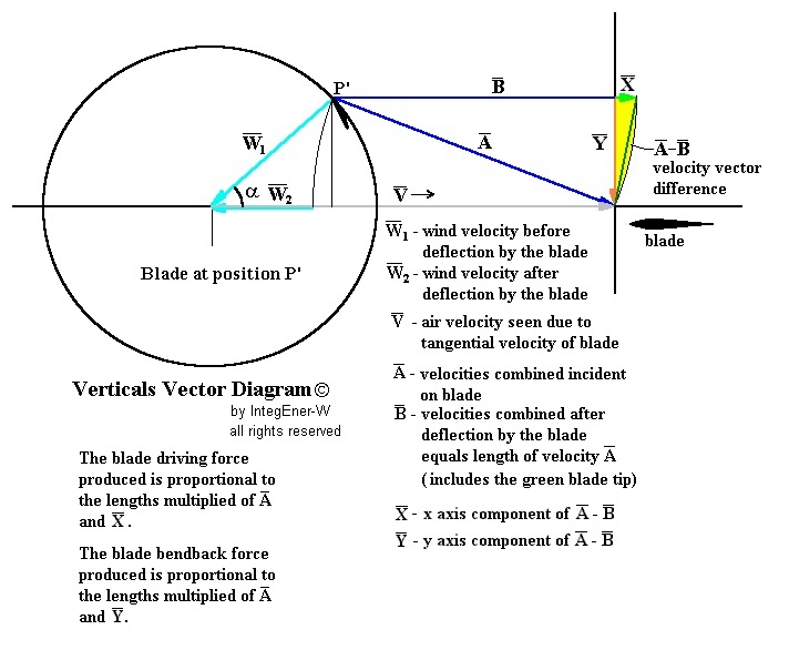
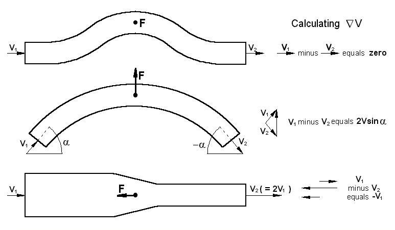
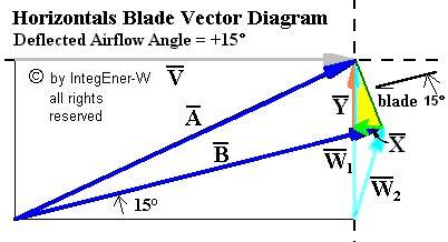
The Wind Energy Blade Vector Diagrams
For reference,
copied in below are the two vector diagrams normally associated with the wind
turbine linear deflection forces method of calculation, the first for horizontal
axis and the second for vertical axis. The blade appears in these diagrams to be
fixed in position in what is known as the blade frame of reference. Looking down
from overhead, the atmospheric wind appears as vector "W1",
entering straight upwards for horizontal axis and entering from various
directions for vertical axis. The tangential velocity due to the blade motion,
"V", is seen as a relative wind from the left. The various velocity vectors are
identified and described within the diagrams.
Note that the "B" vector,
which is the relative airflow seen by the blade after having been deflected by
the blade, is the same length as the "A" vector but is at a new direction, which
is the average direction of the airflow after having been so deflected. This new
direction varies depending on the blade pitch angle. The angle of the average
deflected flow shown in the diagram is zero degrees along the x axis but the "B"
vector angle may have a different value. This will also affect the "A - B"
vector and its components in the diagrams. A supplementary vector diagram below
depicts a "B" vector average deflected flow angle of fifteen degrees above the x
axis. Note also that the atmospheric wind velocity, after contact with the
blade, notated as "W2", changes direction and is reduced,
indicating kinetic energy lost after transfer to the blade. On average over the
rotational cycle, the energy so lost after transfer to the blade for the
vertical axis case is seen as less than that for the horizontal axis
case.
Lastly, note this. Looking closely at these flow deflection theory
vector diagrams, what is revealed is the wind turbine energy generation paradox
that otherwise lies hidden. While the air flow velocity remains the same before
and after passing over the blade in the blade frame of reference (the "A" and
"B" velocity vectors), the air flow velocity becomes much less and even can come
to a halt or near halt in the earth frame of reference (the "W1" and "W2" velocity vectors).
Descriptions
of the various vectors may be found respectively in the vector diagrams above
and below.